Sorry for the somewhat bulky topic, but I didn’t know how to describe it better…
In addition to the request of being able to add grainlines, notches, etc., which are definitely new elements, I think it would be helpful to somehow “mark” lines/points that already exist in draw mode so that they will be printed later on.
My idea would be to add a simple checkbox in the tool options area in draw mode (perhaps named “Print on detail” or so) and if you check the box, the line or point name will be automatically added in detail mode, too.
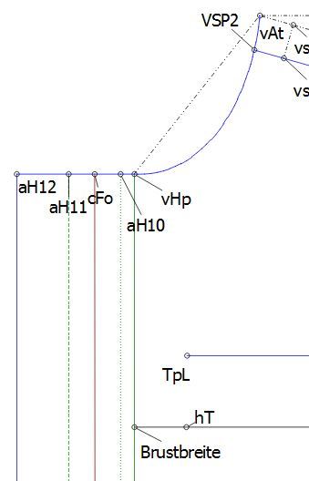
As an example, here is a grown on button placket in draw mode:
The green lines are fold lines and the red line is the main center front as orientation. Now, it would be great if not only the part front line (running down from aH12) itself, but also the colored lines and the point name “Brustbreite” could be printed.
I didn’t open up a new feature request for this, because I’m not sure if the checkbox thing is a good idea… The basic idea here was that it might make development of the printing feature a bit easier in this case if you didn’t have to add a complete new detail element (with all the xml stuff and such) but rather take what you have and only “mark” it for printing. Hopefully you understand what I mean …
Hey Susan, #509, in my opinion, is significantly different. All elements mentioned in #509 are new elements per se, a new path type if you wish (even with different handling of seam allowances, etc.).
My idea is “only” about printing (or not) what is already there!
The most important point for me here is, that it must be relatively easy to develop such a feature - so let’s see it as a first step, if you like. At the moment, the outlines of a part and the selected points are taken from draw mode to detail mode and are already being printed, because they are the essential parts of which a detail part consists. So why not make it possible to selectively mark (see checkbox) some of the other already existing elements and take them over from draw to detail mode, too, but only for printing and not to form the detail part itself…
You see, for me, #509 could possibly be implemented as additional feature set (like Bojan’s great labels) only to be available for parts in detail mode (not draw mode), perhaps as a second layer of part information or so, whereas my idea here couldn’t.
I can’t describe the difference (for me) any better, sorry…
(Step 1) From what I understand, when the user creates a new detail part via GUI, you really “only” save the point/spline/line ids as “node idObject=” elements to its parent detail element and then create the visual representation in detail mode based on the information of those ids. These points are necessary for you to create the detail part itself, like it is done at the moment.
(Step 2) Now, when I say, “I’d like to take additional lines or points and mark them to be part of the detail part and which will be printed later on”, I’m talking about saving additional “node idObject=” elements to the parent detail element. These point/spline/line ids also do exist already in the drawing now, but aren’t part of the details outline and therefor not necessary for creating the detail part itself -> that’s why they weren’t chosen in “Step 1” when the user created the detail part.
I tried to understand your code and that’s what I came up with (please call me noob if I’m totally wrong):
At some point you must send all the actual point data to the underlaying visualization engine to actually draw them onto the scene layer.
I tried to follow your code to understand how everything works. Everything is based on the pattern data, from where you get your information about the points. For a detail part VDetail::ContourPoints and ::ContourPaths (and corresponding seam allowance points/paths) contains the data that is necessary for this. As points are QPointF objects, they contain the actual plane coordinates. This must be true for every point of every part in draw mode, not only the ones you use to actually draw the detail part.
From this I thought it could be possible to add a i.e. VDetail::PrintEgdes for single lines and ::PrintPoints for single points (see Step 2): PrintEgdes results in single lines or curves and PrintPoints only prints a dot or a cross with the associated label. All coordinates should be there already, too, so I don’t understand your positioning problem. But perhaps it is me not understanding how you create point coordinates and why it’s not as easy as I think…
…
Issue #509 contains a different, totally new kind of data for me (maybe we need a new tool to create the new line types, perhaps) that is not there at the moment, that’s why I think it is different from my proposal…
Issue 509 was specifically created to allow facing lines, dart lines, pocket placement lines, and others to be included on a pattern. These objects must already be created in Draw mode. Issue 509 describes a feature to display these objects in Detail and Layout mode. The word ‘Enter’ was used, but ‘Select’ was what was intended. The styling of the objects in Draw mode is to be retained in Detail & Layout modes (line thickness, dash definition, but not color).
Enabling ‘Internal Paths’, paths which are not are not part of the SeamLine/CuttingLine object, is the difficult part.
The issues list contains proposals for new tools which will help to to more easily create complex objects like Tucks, Darts, Pleats, etc… Each of these tools will include a default-style user setting, so that a designer can define their preferences and have continuity between patterns.
The Grainline tool is next on our list of TODOs. Like the Seam Allowance tool, the Grainline tool creates an object which exists only in Detail mode. It is an internal path, so many if not all of the technical issues will need to be solved.
hey @pandel , Hopefully you don’t feel that there’s argument here. YOUR SUGGESTION IS AWESOME!
We have had so many discussions that we have to tie discussions together when they are related. it helps everyone over time.
Your remarks are spot on, Issue 509 could have been written more precisely.
Hey @slpencer, everything is fine !!! Sometimes it takes some time to discuss different viewpoints. But I love that , even though discussion gets a bit hotter…
I think, I now understand better why you think, that 509 and my proposal are close up. You’re right, new things and already existing things are mixed there…
Enabling ‘Internal Paths’, paths which are not are not part of the SeamLine/CuttingLine object, is the difficult part.
I got it, but I’d have liked to know, why ;), as I thought, because it’s about already existing objects, coordinates and such things to draw them (in fact, they are already drawn → in Draw mode, but not in Detail mode) are actually there…
Issue #24Label on Detail had to resolve many of the issues faced with displaying objects within the center of a pattern piece in Detail mode.
Hopefully this will get us further on our way towards a complete software package.
If you understand code, please make a fork and fix a small issue with Menu. After your code is successfully merged, you pick the larger issue that you really care about. This is open source, your code contribution is required to make this project real!
It’s a false impression that open source is FREE as in BEER. Open source is a bartered economy. Users contribute translations, training videos, and code instead of cash if they want the software to be completed.
I’m only able to partly read C++ code, but am unable to actually write some … I feel very sad about this, really… At the moment, I’m trying to understand what Bojan has done in #24 as a first step…
Totally understand, many of us are in the same situation. There are many ways to actively contribute, and we’re super thrilled that you are interested in Valentina.
my english is not that great.
but i think im in the right topic.
i want to print my drawing with some helplines and markpoints.
is that possible? or can i only print the pattern itself?
is there an easy way to help me out?
for lingerie the help lines are verry usefull somethimes.
thanks
hi,
thanks for answering so fast.
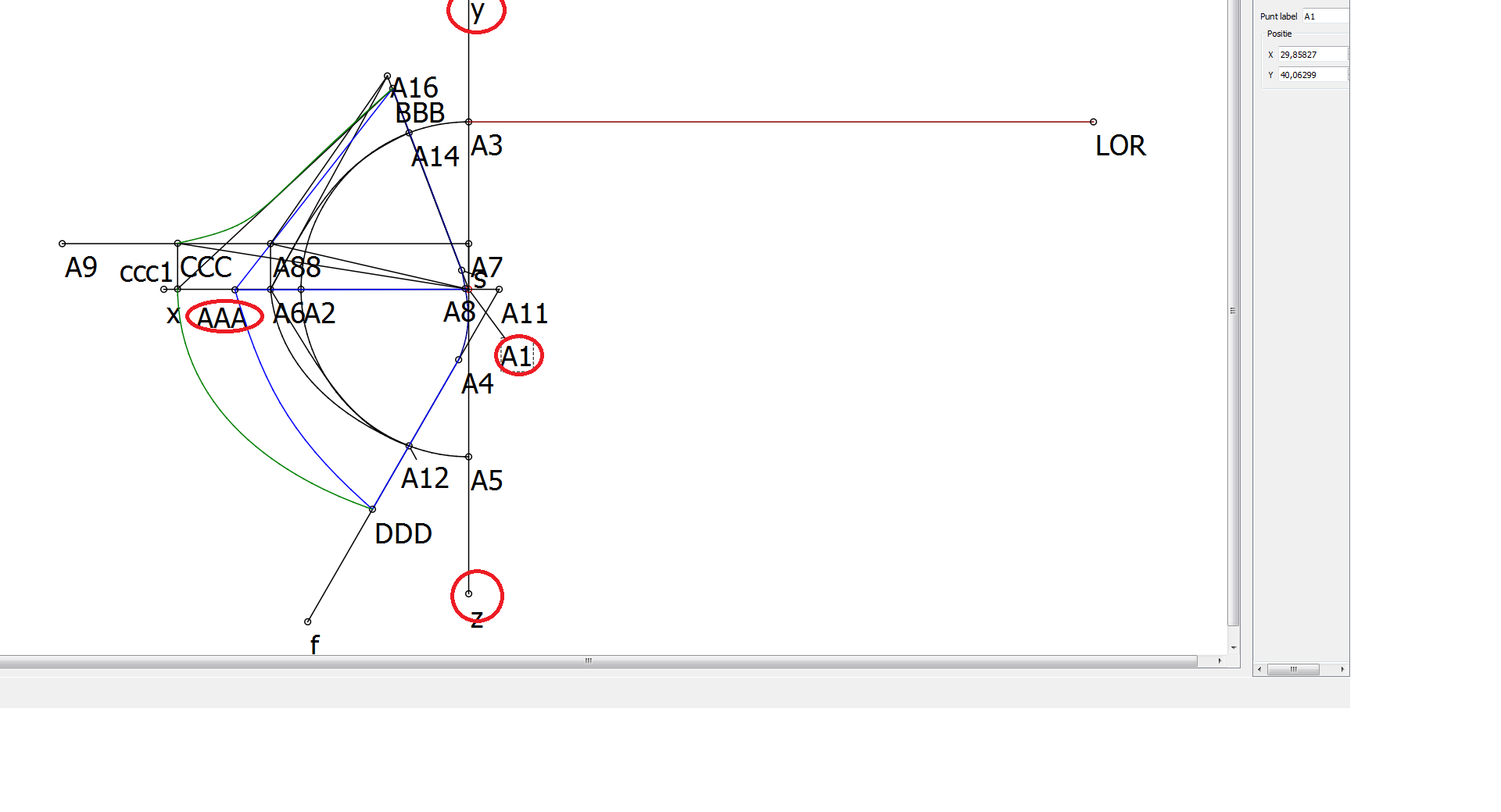
i would like to see the horizontal (AAA-A1)en vertical line(Y-Z) on my print.
mainly point A1 is verry important.
now i can only print the pattern itself ans the seam alliance.
Okay, i think i understood. Unfortunately right now no, you cannot. Watch issue #509. Right now i am doing redesign that will bring this feature. Watch my progress in thread Redesign Seam allowance tool.
@pandel, In reviewing this thread I understood what you want by wanting objects to “self-identify” for automatic inclusion in the detail pieces.
There are two issues that would need to be addressed:
There can be multiple Detail pieces per Draw mode piece. To which detail piece would the object belong? A Detail piece doesn’t exist until the user explicitly creates it by creating the seam line with the Seam Allowance tool.
There are two types of lines in the Detail piece:
— Seam lines. All objects in the seam line must be physically contiguous, in clockwise order, and no repetitions. How to ensure the object is placed correctly in the ordered list? As far as having different line styles along the seam line, so that semantic info about seam treatments or other info is represented on the pattern image, this is something I have wanted for quite some time.
— Internal lines. (This has been recently implemented during the redesign.) This idea seems fine for internal lines, other than determining which detail piece the line will belong to.
@slpencer, after reading this whole thread again, I think I also understood something:
Previously I thought that “creating a Detail piece” is (more or less) using the seam allowance tool to mark/unmark lines and points of a pattern piece as “don’t hide them in Detail mode” and then simply redraw those in Detail mode and add some additional seam allowance lines. From what you wrote I assume that a Detail piece is really re-created in a more algorithmic way, so my wish to have some of the lines or independent points to be printed later isn’t simply that easy and I do understand that now.
Taking this into account, your issues are quite more complicated as I would have thought before. This “self-identifiying” mechanism then couldn’t simply be integrated in draw mode as a global “print this” checkbox (as I thought in the beginning of this thread), but perhaps it can be added to the seam allowance tool (which today is more a “detail piece creation tool” with all its additional features). And this would make an object belong to a single detail piece.
I have no idea at the moment, how to possibly address the questions from no. 2 of your post, especially for the interal lines (which is a HUGE feature addition, btw)…
Agree. The Seam Allowance tool is not about the seam allowance per se. It’s purpose is to define the seamline, the objects along the seamline (notch points, ease/gather marks, etc.), the objects within the seamline (labels, grainline, internal lines), and the width of the seam allowance outside the seamline.
 …
… … I feel very sad about this, really… At the moment, I’m trying to understand what Bojan has done in