Which is going to be more numerous than with mens or womens patterns.
I’d propose theres another option… that is figure out if grading rules for dogs could be applied like I did with the Shift Dress pattern. Where a base pattern could be draped or drafted, fitted, tweaked, input into Seamly… and then graded as per measurements in SeamleME.
In anycase… I don’t think drafting a pattern for a dog would be different than people, where you need to make a curve the length of a measurement. The curve is going to be proportional to other measurements that can directly be drafted. For Ex… the neck of a mens jacket is (generally) proportional to the chest.
Hmmm… maybe off topic, but maybe not. Don’t know if you’re familiar with the Wild Ginger software, but it has the feature that checks if measurements add up or are valid. Wonder if we could add some sort of measurement checks to Seamly2D? Using the neck example… somehow add a check to see if the drafted neck is >= the actual neck measurement in SeamlyMe.
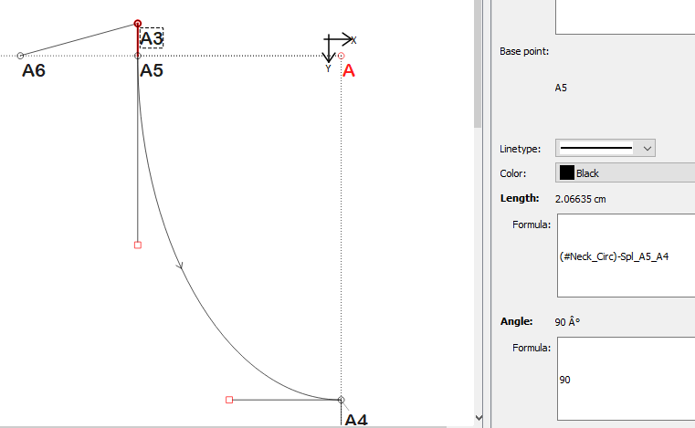
I was thinking that one could have an extension line that will lengthen & shorten according to the difference between the neck measurement & the chord measurement with this formula: (#Neck_Circ)-Spl_A5_A4. Then this will determine the slope of the chest seam (which will also need to be a measured depth).
And yes, I would approach it in exactly the same manor as making clothes for people.
Personally, I think this isn’t feasible. that would mean that even the warning will need instructions as to what it needs to compare to, so I think the line with the length of the neck circ & the length of the curve is a good enough comparison and not too hard or messy to do.
Why would it not be feasible? What I’m proposing is more comprehensive data validation process, where 1) It could check for ex if a resulting line or curve length (such as a neck circ) is less than a direct measurement - if so you would be notified so you can make corrections. 2) It could validate measurements entered. For ex: if a nape_waist + waist_floor > nape_floor… something is wrong.
I can definitely see how it will work at the SeamlyMe level, & could eliminate the need for an extraneous point to use as a metrometer, comparing Spl_A5_A4 to Spl_A5_A7 would just be a case of clicking on the splines, same as grouping, but I’m not seeing how it will eliminate the need for entering (#Neck_Circ)-Spl_A5_A4. & would it add a gauge to the sidebar, or just function as a dummy-light?
I’m a bit late to the party on this thread (I’m new). I thought I’d share an alternative approach I haven’t seen mentioned; I apologize if this has been discussed elsewhere.
A few folks have correctly pointed out that it would be really hard, if not impossible, to find closed-form formulas for points or bezier curve handles that will satisfy arbitrary constraints in terms of other pattern variables. @sjoerdg and others recommend an iterative trial-and-error approach instead:
Here’s my suggestion. There is in fact a way to formally and efficiently automate this trial-and-error approach using gradient descent. The user would specify a “loss function” for the solver to minimize, and choose the variable or quantity for the solver to manipulate until convergence.
For example, to match two curve lengths, the loss function could be something like (curve_A_length - curve_B_length)^2, which is zero when the lengths are the same. Maybe the input to manipulate would be a curve handle angle or starting point coordinate.
An excellent illustration in a different software package, albeit one that is probably more sophisticated than Seamly needs, would be the Excel solver. Youtube has a zillion demo videos if you’re unfamiliar.
The beauty of this approach is its generality. There’s no need to build a whole library of all the different possible constraints. Instead you get 95% of the constraints you could ever need by adding a single feature. This approach also fails elegantly when a constraint can’t be satisfied at all, by getting as close as possible.
Edit: To be clear, this approach would need extra code to need added to Seamly before it can be used. I’m not sure how hard it would be to build. The main ingredients are there: mathematically the technique is very well understood and Seamly already has an expression language and variable table. But there could well be idiosyncratic design issues lurking in the Seamly code base that make this hard to implement.
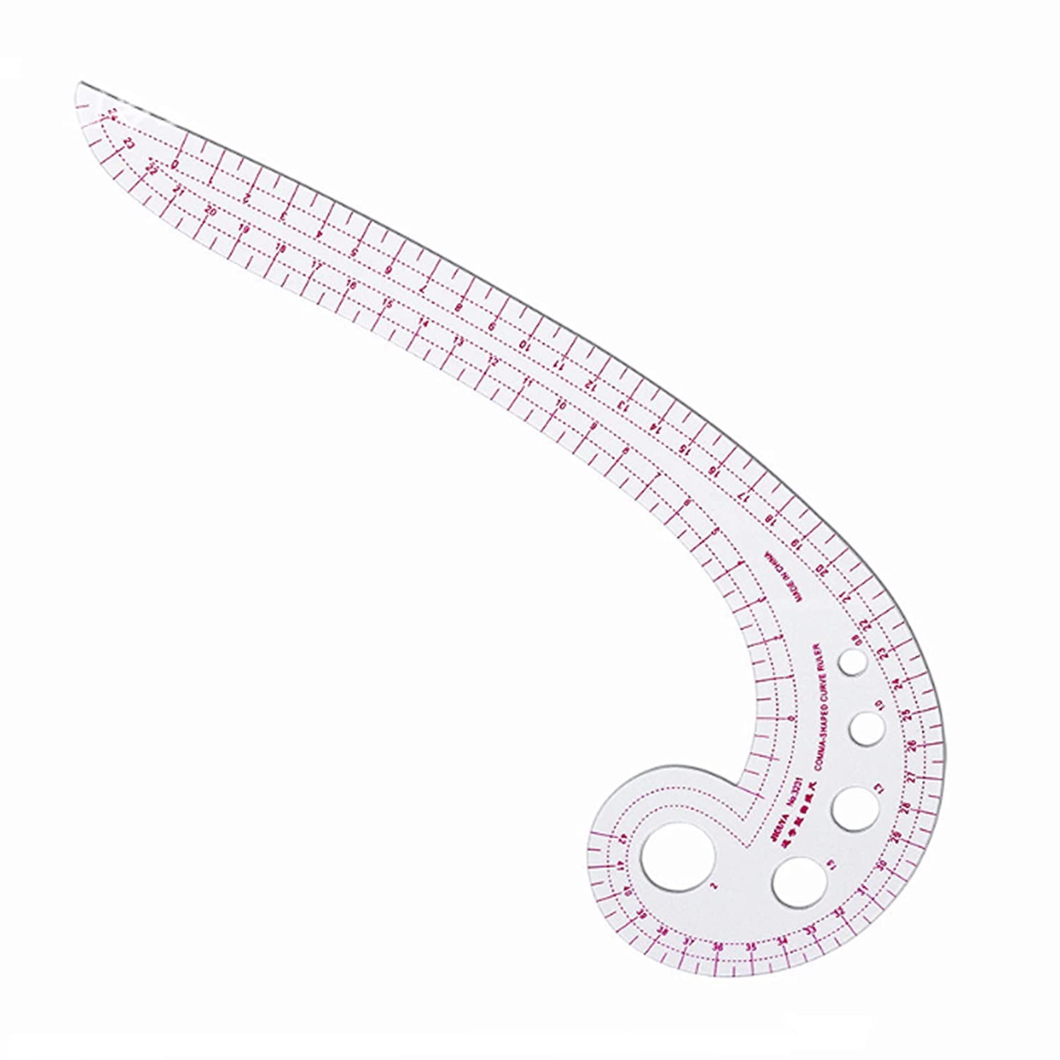
As I pointed out the issue goes beyond just matching the length of 2 curves… pattern making also requires matching the shape of the “seams” in the right places. I say seam as it could be matching a curve & curve or curve & straight line. That’s why they make tailoring tools like this:
Not worth my time right now. Time can be better spent on more useful features.
Yes. Like I said… make no assumptions about the project,
So many before (myself included) have thought “oh just do this” it’s easy. It’s not. It would require overhauling a lot of the tool files, the tool visual files, the tool dialog files, the pattern & dom doc read/ write routines, the pattern file schema (possibly the ME schema), updating the xml files to convert old patterns, the undo commands, adding new classes, and a bunch of stuff I’m not even thinking of. Not to mention the Pattern Cloud should also then be updated.
One little change in a tool can ripple through the whole application, especially if it reflects in the pattern schema.
That being said… I think what might be useful, and easier to implement is a ruler tool that would interactively compare the length between a group of selected nodes to another group of selected nodes, and if necessary the user could then adjust the pattern to match the 2 groups. If implemented in the right way it could be used for a whole bunch of other uses… which I’ll leave for future discussion.
Yes, I agree. The length example was intended to be simple. This approach would be able to work with any well-behaved characteristics of the pattern, including seams composed of shapes like the french curve in your figure. (To be more precise, and please excuse the jargon, but by ‘well-behaved’ I mean any continuously differentiable bounded real-valued properties of the pattern, whether actual parameters or functions of parameters.)
Ah… my post wasn’t intended as a feature request, and I certainly wasn’t asking you to do work. Sorry if I miscommunicated. (Or, are you saying that PRs of this nature would not be welcome? That would be useful to know!)
Yikes! That seems like a lot.
I’m afraid I don’t completely follow, but then again I don’t have the background or experience you do so perhaps I shouldn’t expect to!!
[quote=“hyperthreaded, post:30, topic:6067”]
(Or, are you saying that PRs of this nature would not be welcome? That would be useful to know!)
[/quote
No… I’m just saying it’s not something I deem neccessary at this time for myself to invest time in. But if you want to try , go for it. I’m just warning you it’s a monstrous task. As previously noted changing the curve tools as you suggested would involve just about ever aspect of the pattern code. It took me 4 years (part time) deciphering the existing code to get where I am. Personally… I’d suggest looking through the issues on Github and pick an easy one to work on first.
Yes it is. And it requires a good understanding of Qt’s signals and slots as there are probably thousands of connections between widgets and/or data. Oh… that’s another one I forgot… the data container.
In a nutshell… if there was a ruler sort of tool it’s possible it could also for ex be used to measure a path to obtain the length of a needed trim which could be incorporated into spec sheets. Again, a topic for a future discussion.
Trust me… I’ve been down many a rabbit hole with the app. You start to realise pretty quick theres more to it than one originally thought. For ex… if you read my recent post on the move tool I’ve been updating - in testing I realised the operation tools were not updating the History. Yup… there’s another area that tools affect. For me it was an easy fix, because I’ve been down that hole before.
Ahh… yup. Theres a few reasons why it’s hard to navigate … 1) It’s mainly written in a puesdo Russian-English with lots of ill named variables, methods, and abbreviations. For me at least it’s hard to read when everything reads backwards. For ex… in English we would say blueBallComboBox… not comboBoxBallBlue. I could go, but you probably get the point. 2) There’s too much of code style variation - even sometimes within a single line of code by the original dev. Nobody was really keeping tabs on style standards. 3)Too much bloat that serves no purpose 4) Lacking in helpful comments 5)Just the nature of the beast… there’s just a lot of moving parts, and you have to understand the structure of the apps to successfully add or modify a “tool”. 6) You need to have good grasp of the Qt framework - especially the graphics, DOM documents, and ui forms.
That being said… I’m old school. I was taught that like 90% of programming is reading 10% actual coding. If one can’t read the code it takes that much longer to get a task done. I also programmed in 68000 assembly for years, so I’m a minimalist when it comes to coding… if it doesn’t serve a purpose it shouldn’t be there. Just more crap to read through.
As they say, ves’ kod – eto ustarevshiy kod. All code is legacy code. And yeah, style inconsistency is a pretty common hazard in C++ land. Over the language’s long lifetime it has evolved beyond recognition and we’ve learned a lot about how to program in-the-large as an industry.
Of the points you raise, the thing that really concerns me is an implied lack of separation of concerns: adding a new tool shouldn’t impact so many irrelevant parts of the codebase. As you’ve emphasized a few times in this and other threads, that will really slow the project down and make it hard to maintain quality. For one thing, it makes automated tests brittle. And as you’ve pointed out, even small changes demand that the programmer understand and reason about far too much state and too many moving parts.
My interest is in using solvers and generative models to produce patterns subject to constraints. I had been planning to dive in and experiment using the seamly code as a pattern engine, but it’s dawning on me that maybe I should play in a safer and simpler space for the time being.
Thanks @Douglas for your patient explanations and wise advice in the face of my naively optimistic posts!
Like I said… spaghetti code. Aside from the issues of not following UI standards (for Windows) and all the misnaming of industry terminology (much of which I have or will shortly have fixed)… there’s not even a separation of the UI from the codebase. Parts of the UI is constructed programmatically rather than through Creator, so you can’t even separate the “art” from the “science”. That is you have to know how to do both to even use a tool dialog. Slowly I’ve been moving some UI widgets to custom promoted classes so forms can be designed in Creator without having to worry about how to populate them in the code. For ex the color combobox in dialogs.
Which just reminded me of another part of the “tools” I just thought of… the “Properties Editor”. It’s another 3rd party library ball of wax stuck onto the code. Another whole bunch of rabbit holes. LOL If you add or update a tool, you also need to add to or may have to update the Property Editor code. Unless there’s something I’m missing… since you can edit any tool’s properties through it’s dialog, I fail to see why the Properties Editor library is even needed. Properly done the dialogs could share the same widget layout with the Property Editor dock… but I digress.
So, I skimmed through this a bit and I believe that what you’re are trying to do would not be possible exactly. There’s not really enough information in your pattern.
You’d have to think of it like this: If you make a cone and it has a flat bottom perpendicular to the tip (like a right triangle), if you cut that open to unroll it the resulting shape of the arc is calculable if you alter the height or width of the cone.
If you were then to change the shape of that resulting arc to make it match another arc it would be nearly impossible to find the height and width of the cone that would create it.
Similarly, if you were to inject some kind of bend into the cone or start poking holes in it or something, the amount of measurements you need to take in order to regenerate that shape as you ‘resize it’ increases drastically. You might need 20 or 50 measurements in 3 dimension and angles of the resulting dimensions in three dimensions to recreate the original shape so that it could be properly scaled and unrolled again. You’re no longer “taking a flat pattern and scaling it up” you’re drawing a 3d model of the object that the original pattern fit around, scaling that up, then wrapping the pattern around that again, then unrolling it.
Makes sense to me, but then I have a degree in Civil Engineering, where I’ve had plenty experience drafting things back in high school like truncated cones as a flat piece.
Yes, it also makes a lot of sense to me since I read up on exactly that a few years ago - actually to create the circumference of the cone or tube to fit a hole in a round pipe, which is basically what we’re doing when we fit a sleeve cap to an armhole.
Exactly. Although if it were just a cone and round pipe it would be easy! The “cone” doesn’t need fullness for a cap.
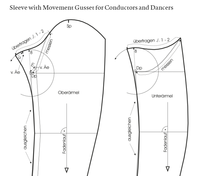
Which is PRECISELY the issue I’m faced with this very moment. I have to recut the top part of a sleeve because it needs more cap fullness. Of course the whole sleeve pattern is compounded by the fact they need built in gussets.
Ah… yes, so they can dance and move their arms around. How would a built-in gusset look on a pattern? and especially a jacket pattern? since the side seam is normally moved a little towards the back. Hmmm… An interesting dilemma
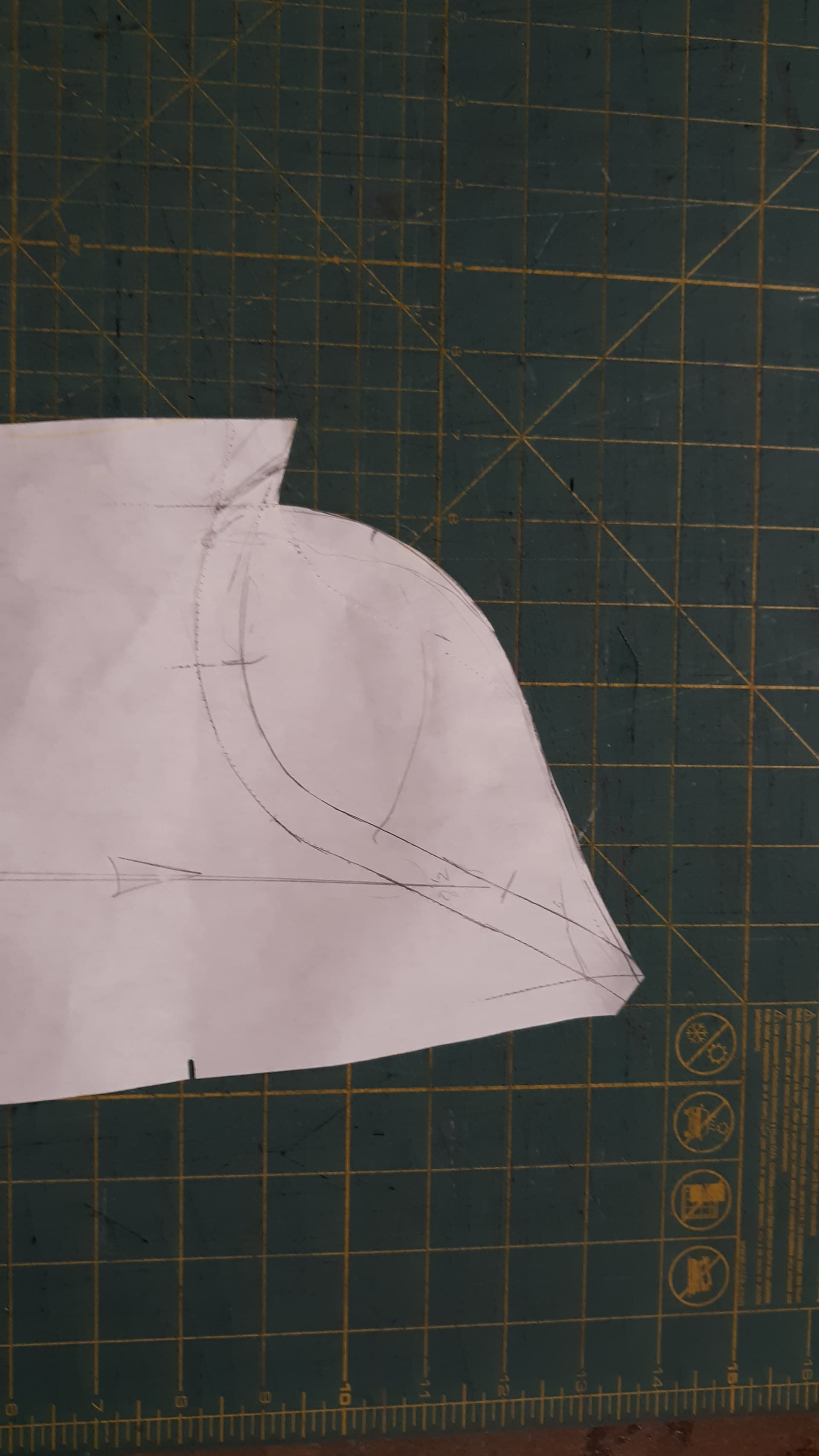
We’ve done it that way, but it looks messy with too much of the gusset on the front with a 2 part sleeve. Plus it puts the gusset on the seam… making it more bulky. Basically what I do now is flip the curve of the under sleeve s ok it creates a football shape that just folds on the lowest part of the armhole. When I go to work later I’ll post a snapshot of pattern.
If you’re dong a 1 piece sleeve, then splitting the gusset at the seam is what you need to do. Of course in both cases you can add a separate gusset piece, but again more bulky in the seams, and more work.
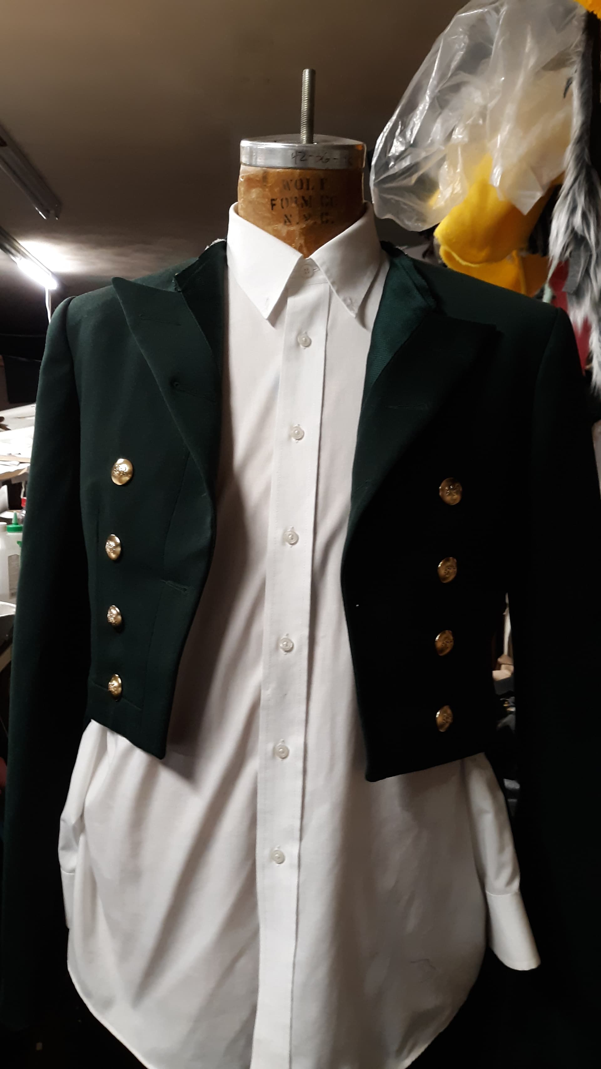
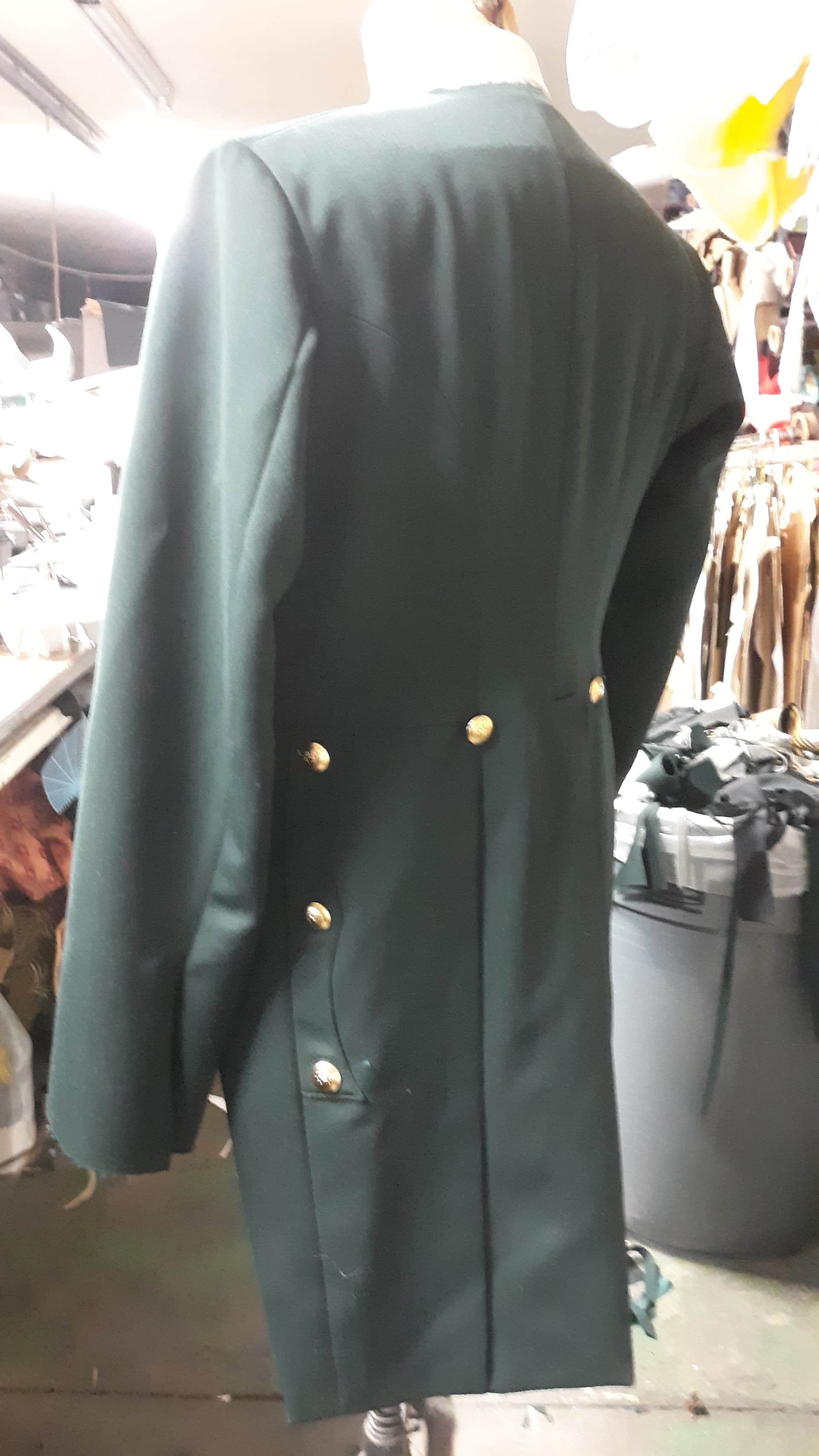
Addendum:
This is what I did: You may also notice compounding the issues we have to deal with are the 1" seam allowances in the under seam to allow for alterations. This is for one of the Livery (Butler’s) coats… that I putting the collar on now.