Hi there! This has been really helpful for me, but I’m still struggling with how to make a point on the end of the section of arc that I’ve drawn and mirrored, so I can then connect these points to other parts of the block. Can you think of a way to do this please?! Thanks in advance!
1 Like
For the drawn section of arc you use the Point along Arc (AA) tool, & set the point to be the name of the arc distance along the arc. This will be showing in the dialog with a format of Arc_[centerPoint]_[number], eg: Arc_A_14 So if I put a point at distance Arc_A_14 along Arc_A_14 the point will be on the tippy end of the arc.
The mirrored arc segment may be dealt with in the same manner, (but it might be pertinent to note that if your master segment was 2 units long, the mirrored segment may be -2 units long.)
I hope that clarifies how to deal with this. If not, pictures might help, either of your particular situation, or of my checking on the process.
Best wishes!

1 Like
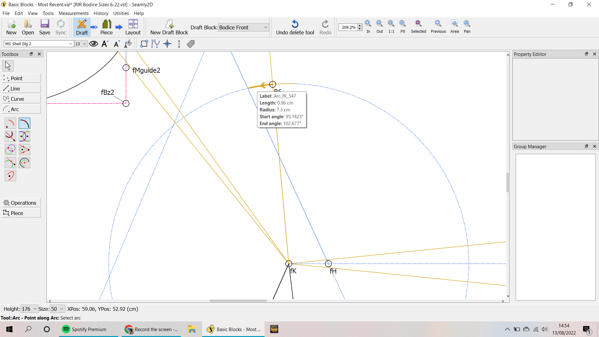
Thanks so much for getting back to me so quickly! I really appreciate the help. For some reason it’s not putting the point on the end of the arc though, and I can’t for the life of me understand why! I’ve screenshotted the steps I did: So, it’s this arc I want, which I select with the Point Along Arc:
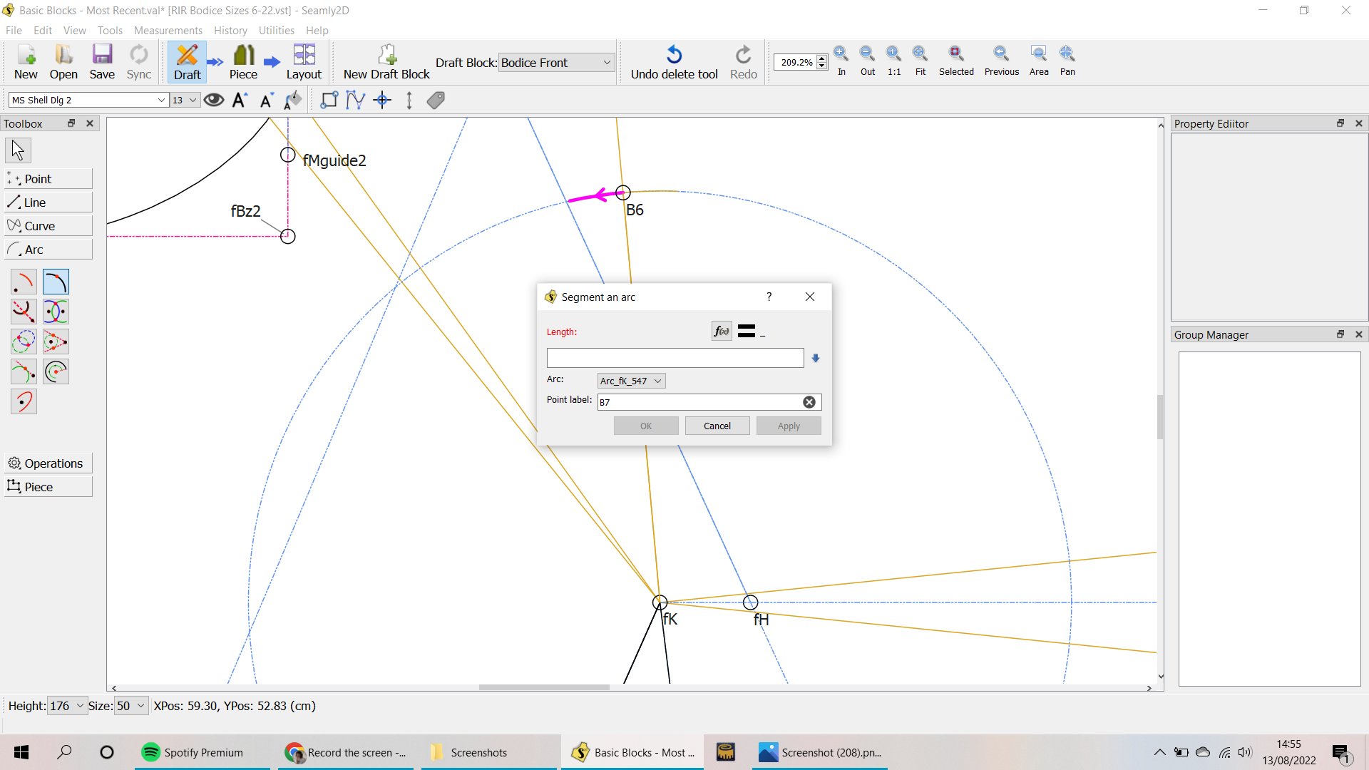
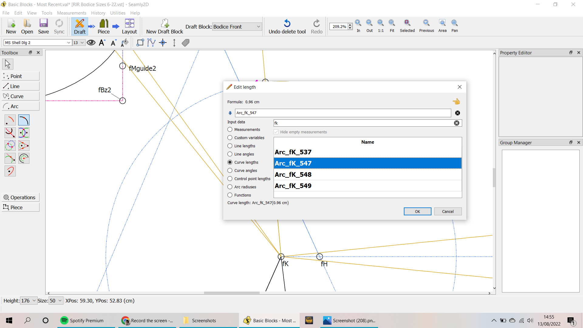
And for the length I select the length of the arc…
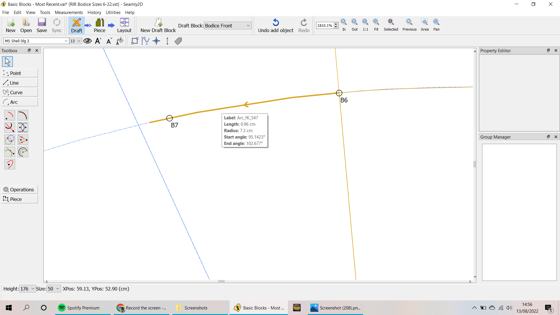
But the point isn’t placed at the end of it when it appears…
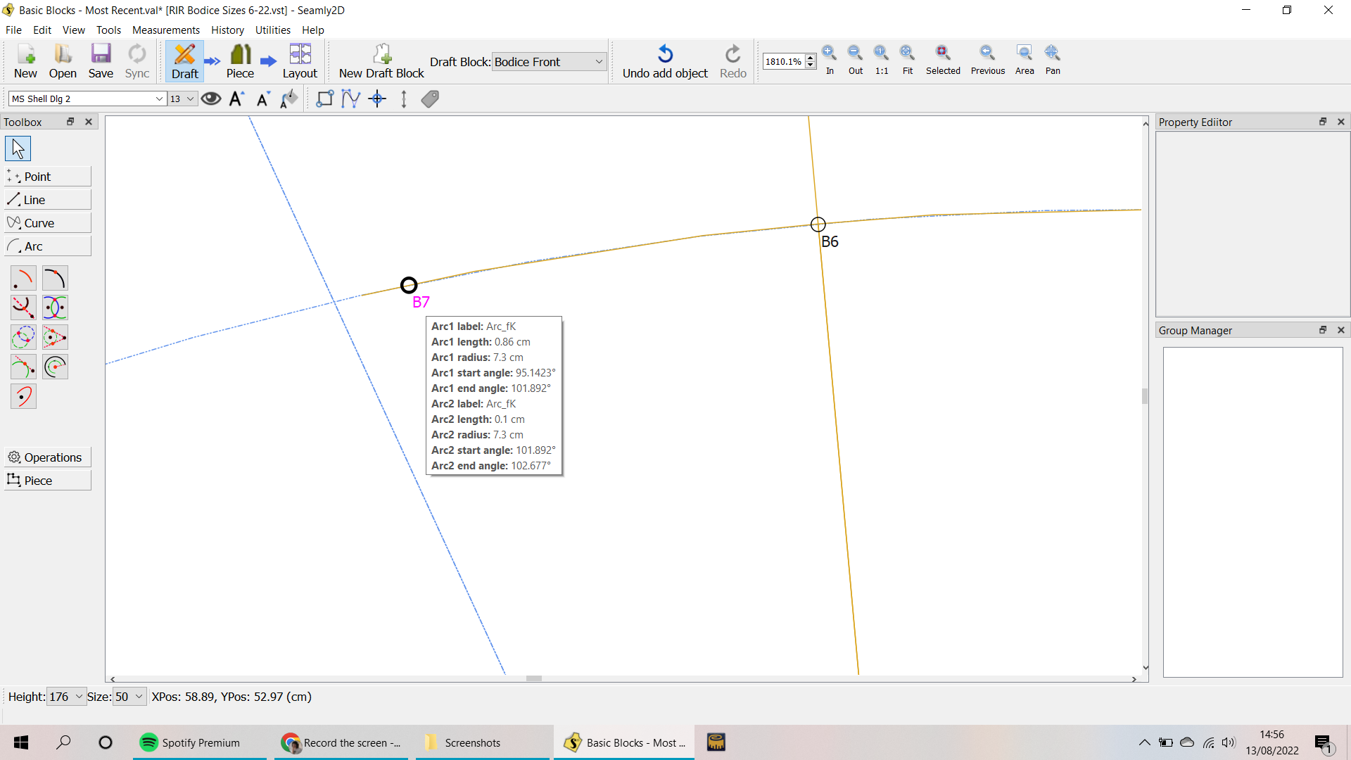
I don’t know if I’m being stupid but I just don’t understand it! Any thoughts?
2 Likes
Ahh. I see now. The bad new is you aren’t doing anything wrong. I think @Douglas made a comment about why that is some time ago, but I can’t find that post right now. My only solution is, if millimeter tolerances matter in your pattern, I see that the point gets placed exactly a mm in, so if you added a mm to the formula for making Arc_fK_547 it would come out how you wanted. If mm tolerances are tolerable in this portion of the draft, it’s probably best to just be disgruntled at it & hope it will be eventually fixed, (& try not to look at it closely.)
2 Likes
Could you post your pattern and any vit and I can take a look at it?
Yeah… I know I addressed this before, can’t recall if it was something I fixed and was justing waiting to push the changes? Off the top of my head I do seem to recall this might be one of those fuzzy math things, where with the floating point math you can’t rely on 2 values exactly being equal, so the 1mm might be the tolerance when comparing 2 points.
3 Likes
That does seem likely. I have one pattern which had an intersection axis & arc neatly formulated to appear right at the end of the arc, only it would fail by a hairsbreadth with certain measurement files. I extended the arc by either a tenth of an inch or a couple hundredths, or maybe it was a similar portion of a degree, —it was a bit more than the apparent minimum— & haven’t had a problem since. But it was either a cape or a skirt, & so very tolerant.
1 Like
In reality… the width of marker chalk or pencil is wider than the fuzzy tolerance. Heck… if you tape tiled pdf’s together your likely to be off more than that. ![]()
1 Like
Thanks so much for taking the time to help me with this! It’s nice to know I’m not just being stupid and not being able to make it work, hah. Here is my pattern, it’s the Bodice Front that I was working on:
Basic Blocks - Most Recent.val (53.7 KB)
And here is the measurements file:
RIR Bodice Sizes 6-22.vst (5.3 KB)
1 Like
(I totally agree about the tolerance being something that can be worked with, it absolutely doesn’t matter in reality if something is only a mm out! But it just makes me worry when something doesn’t work exactly that I’ve done something terribly wrong!)
1 Like
Also, I just tried adding a mm to the formula (as recommended by @Pneumarian above) and the point stayed in the same place! So weird.
1 Like
hmm, it worked for me just now with your file, I think I failed to properly clarify what I was saying. Here’s your file, with my edits: Basic Blocks - Most Recent.val (53.7 KB)
Note that I changed the point placement formula to what the arc length formula had been, so that when floating points become more grounded, (pretty sure Seamly will need to be re-coded for trinary computers before then,) your point won’t get back out of line.
2 Likes
Ahhh okay, I had added the 1mm onto the point placement formula rather than the arc length, but it makes much more sense to do it the other way around; obviously your brain is much more used to thinking along Seamly logical lines than mine, I need more practice! That’s great, thank you so much I really do appreciate it!
2 Likes
That’s what I stick around for! Glad to be of service!
2 Likes
When I get a chance I’ll try and look back through the topics for the one @Pneumarian was referring to… it was a cape pattern that the seam allowance was doing strange things because an intersect point was not on the arc / curve. I just came across my screencaps on my phone I posted while looking for something else. I need to refresh my memory what I came up with, and if I found a programming solution - or not. It was doing this:
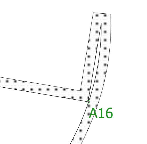
2 Likes
I believe I found that topic… don’t know if it’s the same kinda of issue.
I grabbed your pattern & measurement file. I’ll take a look tonight to see if I can figure out what the issue is.
2 Likes
Amazing, thanks so much!
Ok… got a chance to look at the pattern in multiple versions of the app (I tried an old version before any additions I have made, my most current build, and a version somewhere in between, as well as 2 Valentina vers) , and tested just using a single arc (both methods) and a point along arc at the beginning and the end. There is definently a bug… whether you use the arc length for the end point, or zero for the beginning point, and use either units (inches or cm). The created point is always off by about .0393701 inches from where it should be. Odd thing is the length of a point along the arc is always correct in the formula, but not in the tooltips, variables table or visualization. Hmmm.
It’s gonna take a deeper dive into the source to find where the error is coming from. Stay tuned.
Update: I believe if found the reason, not sure what the solution is. In the CutArc() routine it always has to return 2 arc segments, with a minimum length of 2 mm. So whether it’s the beginning or end, it appears the point will be off at the start or end point by 2mm. Since it’s real numbers, I could try some obsurd value like .0000009 mm… which in pixel land should put it at the start and end. 
I should also note, the cut spline or elliptical arc is a bit closer at 1mm, and that a point along a line does not have this issue.
2 Likes

I haven’t gone through the whole routine yet, but there’s probably some reason why one of the arc segments can’t be zero. Not sure why RT picked 2mm and 1mm as minimum lengths though , when it seems like some extremely small value when rounded could yield 0 or the length of the arc. I’ll try some different values and see how close we can get it.
2 Likes
Thanks so much for looking at it guys, really appreciate it! And it’s very nice to know its not just me who can’t make it work, ha ha
2 Likes