As a new user I have been enjoying playing around with Seamly! My first impressions are of a terrific product.
I have a question about a behavior that was surprising to me, and wondered whether it’s a bug or a feature.
The cubic Bezier splines tool seems to use the wrong control point angle for segments beyond the first one. It seems to use the reciprocal angle of the previous control point rather than the one that is set.
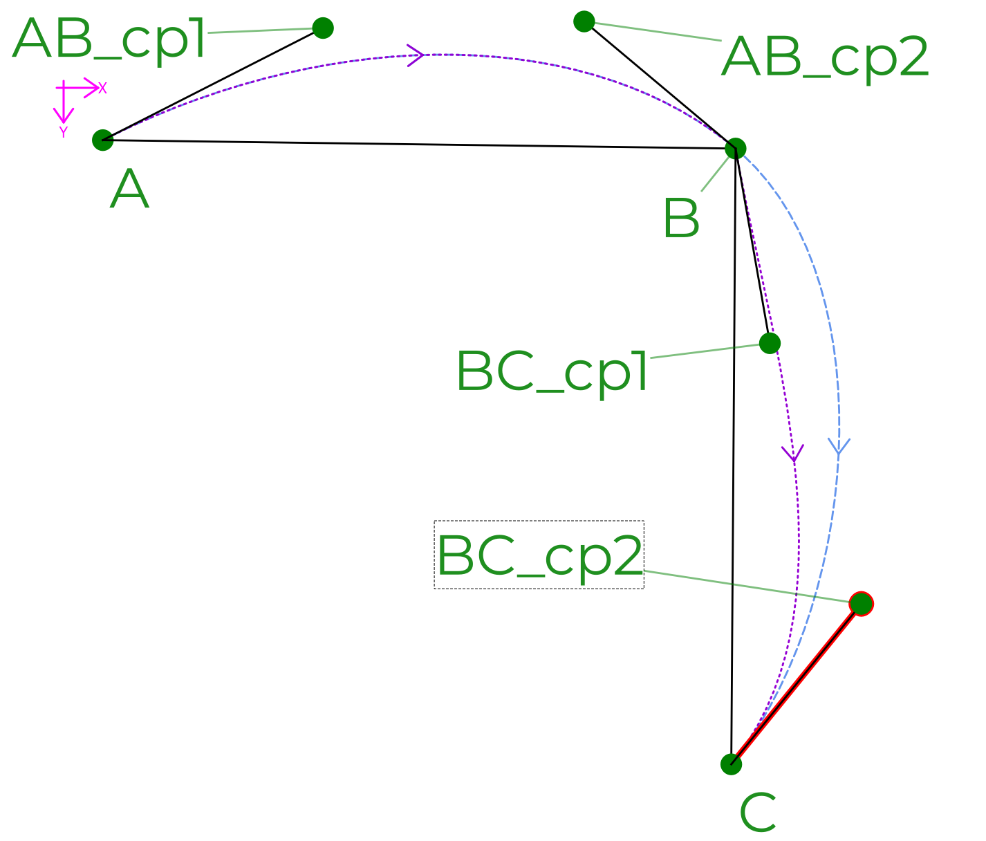
Here’s a minimal example. The spline ABC (dashed, light blue) uses control points AB_cp1 and AB_cp2 for the first segment and BC_cp1 and BC_cp2 for the second segment. Based on experience with other software and in mathematics more generally, I expected the resulting curve to be identical to the union of the two single-segment cubic splines AB and BC (same control points; dotted purple). However, the second segment of the bezier spline is quite different, and the effective control point at B is not actually BC_cp1.
It turns out that the second segment is taking the length of the assigned control point (B to BC_cp1) but the effective control point angle angle is 180 plus angle(B, AB_cp2).
My question: is this the expected behavior? If I want different control point angles in my patterns, should I just use a sequence of individual cubic Bezier curves, like the purple dashed line?
Thanks very much!
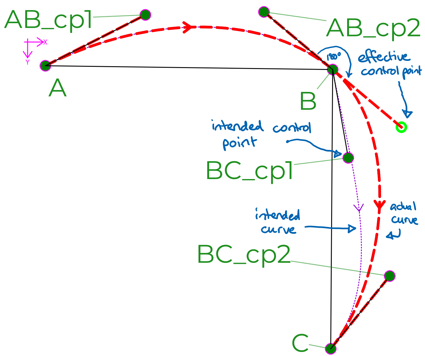
Edit: here’s an annotated version of the above diagram, to clarify which are the intended and resulting curves.
Definitely a bug, the control points on either side of a mid-point using the Spline tool should be stuck 180° apart at all times, both visually & mathematically. Which release date are you using? Does it still let it appear to vary when you restart Seamly? There’s a good chance that @Douglas will want to see a copy of the misbehaving pattern.
Why would it be setup like that? Because the times when one would want a sharp angle in the middle of a curve are virtually non-existent. In all my YouTube watching, I can recall a few times when a pattern had to be altered to eliminate an angle in a middle of a curve, but none where an angle had to be induced in order to achieve a good fit.
So yes, it is intended that if you want an angle between two curves you will have to use the simple Curve tool twice. If I remember my definitions right, Curve is a spline between two points, while Spline is a spline passing through one or more points.
Thanks, Pneumarian. I now see that the behavior I described is intended, i.e. a feature not a bug.
Funnily enough this came up because I am replicating an existing pattern with splines where control point angles aren’t 180 degrees apart! Never mind, I can work around it by using a sequence of cubic Bezier curves (“curve with control points” in Seamly parlance).
The 180 degrees restriction just means that Seamly can only express a subset of possible cubic Bezier splines (those with continuous first derivatives), unless you build up the curve with individual segments. As far as 2D graphics and CAD packages go that’s an unusual restriction, but probably reasonable for this domain especially since there’s a workaround.
It might be worth adding some kind of notice in the UI that this is happening, perhaps in the dialog box for defining a curve. It wasn’t at all clear to me that only the magnitude but not the angle of the second control point would be considered.
A (cubic) Bezier curve is a continuous parametric curve defined by four distinct control points. A cubic Bezier spline (or composite Bezier curve) is a piecewise continuous curve made up of a sequence of Bezier curves.
Have no idea what you mean. The spline path tool is currently programmed to add / subtract 180 to the “other” control point angle when the one of the angles are changed - with the exception of the start and end nodes which only have 1 control point.
It’s not a bug, it’s a feature with an expected behavior.
Bezier paths (connected Bezier curves that form a single curve) are “fair” curves" - the curve is continuous at any point along the curve.
In your use-case the point where curves A and B join is discontinuous - the curve breaks at that point - it’s actually two separate curves. The software updates the angle of BC_cp1 to be the opposite of angle of AB_cp2 (eg “AngleLine_AB_cp2 - 180 degrees”) so that together they form a line which is tangent to the curve. This is how it must operate.
For your use case the two curves have to be created separately because mathematically they are two independent and separate curves.
Please excuse the mathematical pedantry, but it’s actually continuous! (I’m lots of fun at parties, ahem.) I think what you’re getting at, though, is that the purple line is not smooth; its gradient changes sharply. It’s fine to make this hard to implement; I think we agree it’s reasonable for a fashion design tool to discourage non-smooth lines. (Unlike e.g. Illustrator, Inkscape, and the SVG standard, which of course have more general applications.)
The reason for my confusion–and this thread–is that the Seamly UI accepts arbitrary control points to be specified, which would suggest that more general curves might be acceptable. But it silently overrides the angle of every other control point, without telling the user. (Notice the difference between “intended control point” and “effective control point”.) I only picked this up because the Seamly output differed slightly from my pattern drafted elsewhere.
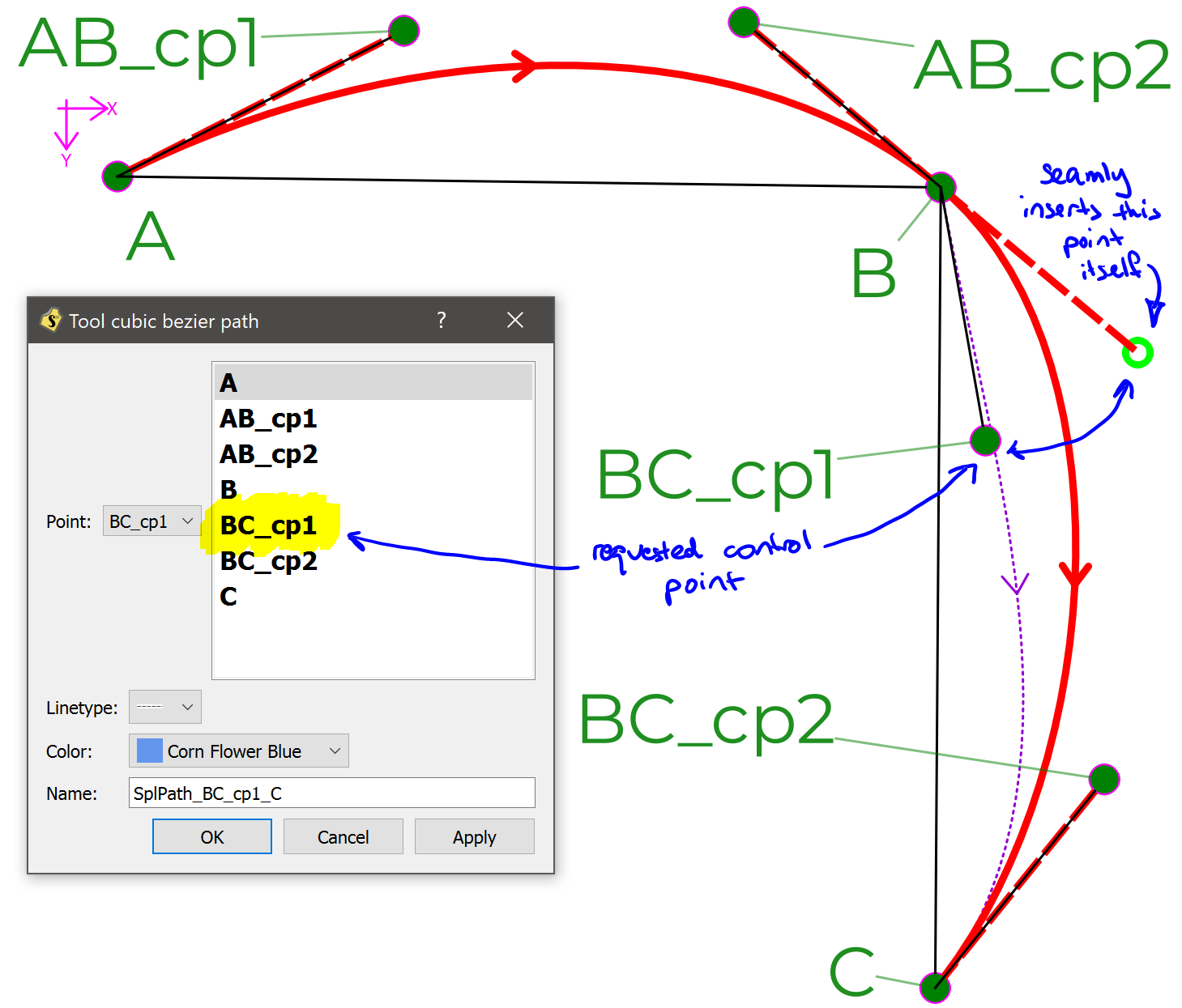
I should perhaps clarify, the image above was made with the “cubic bezier path tool” aka “spline with control points (SP)”, which accepts arbitrary control points, not the “spline” tool. Screenshot: